<

View RSS Feed

The Best of the Internet

  1. CONTROLLING VESSELS and TANKS

    CONTROLLING VESSELS and TANKS © Walter ********, P. Eng., 2001 Sept 07. walter(at)********(dot)ca


    First published in Hydrocarbon Processing , July 1995.


    INTRODUCTION. It would seem that controlling a vessel should be a very simple matter -- They don't really do anything! But then, if they didn't do anything why are there so many of them? And why do they have so many different names? Going through a typical set of Piping and Instrumentation Diagrams (P&IDs) I see the following vessels:
    · Degassing Drum · Gas Separator · Storage Tank
    · Feed Flash Drum · Reflux Accumulator · Day Tank
    · Surge Drum · Suction Scrubber · Slug Catcher
    · Lube Oil Separator · Head Tank · Deaerator
    Although each of these is essentially a simple vessel or tank without any special internal structure, each serves a different purpose. Once it is clear what the purpose of a piece of equipment is, and how it functions, it will also be clear how to control and protect it. Different purposes require different controls.
    SURGE TANKS. The most common function of a vessel or tank is to match two flows that are not identical in time but are expected to average out over the long run. Take a feed surge drum, for example. Flow into the unit is more or less steady but is subject to interruption. The flow to the processing unit should be as constant as possible, avoiding sudden change. Nevertheless, it, too, may be subject to interruption due to downstream conditions.
    The purpose of the surge drum is to maintain sufficient inventory to feed the process and to maintain sufficient void capacity to continue receiving feed as it arrives. Clearly the tank must be large enough to accommodate any normal discrepancies between input and output over a reasonable period of time. Between the upper and lower bound, the exact value of the level ...
    Categories
    Uncategorized
  2. Controlling centrifugal pumps

    CONTROLLING CENTRIFUGAL PUMPS

    [IMG]http://www.********.ca/ce1_cp/1-1.jpg[/IMG]INTRODUCTION. The centrifugal pump is one of the simplest pieces of equipment from the controls and instrumentation point of view. It is a two port device with a well defined characteristic. Its purpose is to provide the necessary pressure to move liquid at the desired rate from point A to point B of the process. Figure 1-1 shows a 'generic' process with a centrifugal pump connected to deliver liquid from A to B.
    Figure 1-2 shows the characteristic curve of an actual pump (a single stage vertical turbine pump) together with the characteristic curve of the process, known as the system curve. The intersection of the two curves defines the operating point of both pump and process. It would be fortunate indeed if this operating point is the one actually specified for the process. It is impossible for one operating point to meet all desired operating conditions since the operating point is, by definition, exactly one of an infinity of possible operating points. In fact the entire point of controlling the pump is to modify its characteristic so that its actual operating point is the one that is required at every instance in time.

    Several definitions are presented in order to discuss the diagram:
    [IMG]http://www.********.ca/ce1_cp/1-2.jpg[/IMG]
    Po = Differential pressure, or head, at the operating point of the pump and also of the process.
    Qo = Flow rate, at operating point, of the pump and also of the process.
    Ppm = Maximum differential pressure across the pump (at shutoff).
    Qpm = Maximum discharge flow of the pump.
    Plm = Static (Minimum) differential pressure between points B and A of the process.


    The minimum static differential pressure of the process is frequently zero, as in a closed, circulating system. If the pump is in parallel with other pumps that are maintaining ...
    Categories
    Mechanical
  3. Centrifugal pump system tutorial

    CENTRIFUGAL PUMP SYSTEM TUTORIAL


    What is total head

    Total head and flow are the main criteria that are used to compare one pump with another or to select a centrifugal pump for an application. Total head is related to the discharge pressure of the pump. Why can't we just use discharge pressure? Pressure is a familiar concept, we are familiar with it in our daily lives. For example, fire extinguishers are pressurized at 60 psig (413 kPa), we put 35 psig (241 kPa) air pressure in our bicycle and car tires.For good reasons, pump manufacturers do not use discharge pressure as a criteria for pump selection. One of the reasons is that they do not know how you will use the pump. They do not know what flow rate you require and the flow rate of a centrifugal pump is not fixed. The discharge pressure depends on the pressure available on the suction side of the pump. If the source of water for the pump is below or above the pump suction, for the same flow rate you will get a different discharge pressure. Therefore to eliminate this problem, it is preferable to use the difference in pressure between the inlet and outlet of the pump.

    The manufacturers have taken this a step further, the amount of pressure that a pump can produce will depend on the density of the fluid, for a salt water solution which is denser than pure water, the pressure will be higher for the same flow rate. Once again, the manufacturer doesn't know what type of fluid is in your system, so that a criteria that does not depend on density is very useful. There is such a criteria and it is called TOTAL HEAD, and it is defined as the difference in head between the inlet and outlet of the pump.

    You can measure the discharge head by attaching ...
    Categories
    Mechanical
  4. Centrifugal pump systems tips

  5. Centrifugal Pumps and Viscosity

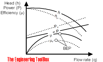
    When a viscous fluid is handled by a centrifugal pump


    • brake horsepower requirement increases
    • the head generated is reduced
    • capacity is reduced
    • efficiency of pump is reduced and the Best Efficiency Point - BEP - is moved


    The head, flow and capacity at other viscosities than used in the original documentation can be modifying with coefficients.
    [h=Flow]3[/h]
    qv= cq q (1)
    where
    qv = flow compensated for viscosity (m3/h, gpm)
    cq = viscosity flow coefficient
    q = original flow according pump curve (m3/h, gpm)
    [h=Head]3[/h]
    hv= ch h (2)
    where
    hv = head compensated for viscosity (m, ft)
    ch = viscosity head coefficient
    h = original head according pump curve (m, ft)
    [h=Efficiency]3[/h]
    μv= cμ μ (3)
    where
    μv = effciency compensated for viscosity
    cμ = viscosity efficiency coefficient
    μ = original efficiency according pump curve
    [h=Power - SI units]3[/h]
    Pv= qv hv ρv g / (3.6 106 μv) (4)
    where
    Pv = power compensated for viscosity (kW)
    ρv = density of viscous fluid (kg/m3)
    g = acceleration of gravity (9.81 m/s2)
    [h=Power - Imperial units]3[/h]
    Pv= qv hv SG / (3960 μv) (5)
    where
    Pv = power compensated for viscosity (bhp)
    SG = specific gravity of viscous fluid
    Categories
    Uncategorized
  6. Maximum designed pump efficiency

    Quote Originally Posted by Esam View Post
    A pump does not completely convert the kinetic to pressure energy. Some of the energy is always lost internal and external in the pump.
    Internal losses

    • hydraulic losses - disk friction in the impeller, loss due to rapid change in direction an velocities through the pump
    • volumetric losses - internal recirculation at wear rings and bushes

    External losses

    • mechanical losses - friction in seals and bearings


    The efficiency of the pump at the designed point is normally maximum and is called the

    • Best Efficiency Point - BEP

    It is possible to operate the pump at other points than BEP, but the efficiency of the pump will always be lower than BEP.
    Categories
    Mechanical
Page 2 of 2 FirstFirst 1 2
1 2 3 4 5 6 7 8 9 10 11 12 13 14 15 16 17 18 19 20 21 22 23 24 25 26 27 28 29 30 31 32 33 34 35 36 37 38 39 40