<

Page 1 of 2 1 2 LastLast
Results 1 to 12 of 16

Thread: Pump and pump system glossary

  1. #1

    Pump and pump system glossary

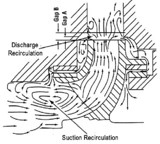
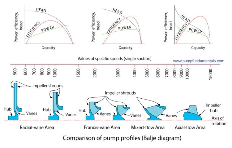
    [h=PUMP AND PUMP SYSTEM GLOSSARY]1[/h]
    [table]
    [TR]
    [TD]Absolute pressure: pressure is measured in psi (pounds per square inch) in the imperial system and kPa (kiloPascal or bar) in the metric system. Most pressure measurements are made relative to the local atmospheric pressure. In that case we add a "g" to the pressure measurement unit such as psig or kPag. The value of the local atmospheric pressure varies with elevation It is not the same if you are at sea level (14.7 psia) or at 4000 feet elevation (12.7 psia). In certain cases it is necessary to measure pressure values that are less then the local atmospheric pressure and in those cases we use the absolute unit of pressure, the psia or kPa a.


    pa(psia) = pr(psig) + patm(psia), patm = 14.7 psia at sea level.

    where pa is the absolute pressure, pr the relative pressure and patm the absolute pressure value of the local atmospheric pressure.

    and in the metric system

    pa(kPa a) = pr(kPag) + patm(kPa a), patm = 100 kPa a at sea level.
    [/TD]
    [TD][/TD]
    [/TR]
    [/table]

    [hr][/hr] [table]
    [TR]
    [TD]Accumulator: used in domestic water applications to stabilize the pressure in the system and avoid the pump cycling on and off every time a tap is opened somewhere in the house. The flexible bladder is pressurized with air at the pressure desired for acheiving the correct flow rate at the furthest point of the house or system. As water is pulled from the tank the bladder expands to fill the volume and maintain the pressure. When the bladder can no longer expand the water pressure drops, the pressure switch of the pump is activated on low pressure, and the pump starts and fills the water volume of the accumulator. The bladder keeps the air from entering into solution with the water resulting in less frequent re-pressurisation of the accumulator.
    [/TD]
    [TD][/TD]
    [/TR]
    [/table]
    [table]
    [TR]
    [TD][/TD]
    [TD][/TD]
    [/TR]
    [/table]
    Pumps are often sold as a package with an accumulator.
    [hr][/hr] Affinity laws: the affinity laws are used to predict the change in diameter required to increase the flow or total head of a pump. They can also predict the change in speed required to achieve a different flow and total head. The affinity laws can only be applied in circumstances where the system has a high friction head compared to the static head and this is because the affinity laws can only be applied between performance points that are at the same efficiency. see

    [link Point to another website Only the registered members can access]

    [link Point to another website Only the registered members can access]
    The following figure shows a system that has a friction head (curve A) higher than its static head for which the affinity laws apply, as compared to curve B, a system with a high static head as compared to the friction head where the affinity laws do not apply.

    Domain of application of the affinity laws for an axial flow pump.

    The affinity laws are expressed by the three following relationships where Q is the flow rate, n the pump rpm, H the total head and P the power. You can predict the operating condition for point 2 based on the knowledge of the conditions at point 1 and vice versa.


    The process of arriving at the affinity laws assumes that the two operating points that are being compared are at the same efficiency. The relationship between two operating points, say 1 and 2, depends on the shape of the system curve (see next Figure). The points that lie on system curve A will all be approximately at the same efficiency. Whereas the points that lie on system curve B are not. The affinity laws do not apply to points that belong to system curve B. System curve B describes a system with a relatively high static head vs. system curve A which has a low static head.


  2. # ADS
    Spons Circuit
    Join Date
    Always
    Posts
    Many
     
  3. #2
    Diameter reduction To reduce costs pump casings are designed to accommodate several different impellers. Also, a variety of operating requirements can be met by changing the outside diameter of a given radial impeller. Euler's equation shows that the head should be proportional to (nD)2 provided that the exit velocity triangles remain the same before and after cutting. This is the usual assumption and leads to:
    which apply only to a given impeller with altered D and constant efficiency but not a geometrically similar series of impellers.If that is the case then the affinity laws can be used to predict the performance of the pump at different diameters for the same speed or different speed for the same diameter. Since in practice impellers of different diameters are not geometrically identical, the author's of the section called Performance Parameters in the Pump Handbook recommend to limit the use of this technique to a change of impeller diameter no greater than 10 to 20%. In order to avoid over cutting the impeller, it is recommended that the trimming be done in steps with careful measurement of the results. At each step compare your predicted performance with the measured one and adjust as necessary.


    [hr][/hr] Air entrainment (ingestion): air in the pump suction can reduce the performance of a pump considerably. The following chart from Goulds shows that even 2% air by volume in the liquid can have an effect on performance.

    Performance reduction due to air in the pump

    There are many causes of air entrainment, the air may be coming in at the suction tank due to improper piping

    or due to leakage iin the pump suction line (assuming that conditions are such that low pressure is produced in the suction line).

    Leakage in a suction pipe under low pressure will cause air to enter the pump.
    Centrifugal pumps can be designed to handle more air if required. Viscous drag pumps can handle large quantities of air.

    [hr][/hr] ALLOWABLE PIPE STRESS: the allowable or maximum pipe stress can be calculated using the ASME Power Piping Code B33.1. The allowable pipe stress is fixed by the code for a given material, construction and temperature from which one can calculate the allowable or maximum pressure permitted by code.

    [hr][/hr] ANSI: American National Standards Institute. A term often used in connection with the classification of flanges, ANSI class 150, 300, etc. See this

    [link Point to another website Only the registered members can access] [hr][/hr] ANSI B73.1: this is a standard that applies to the construction of end-suction pumps. It is the intent of this standard that pumps of all sources of supply shall be dimensionnally interchangeable with respect to mounting dimensions, size and location of suction and discharge nozzles, input shafts, baseplates, and foundation bolts.
    This next image shows the dimensions that have been standardized (source: the Pump Handbook by McGraw-Hill)

    This next image shows a cross-section of an end-suction pump built to the B73.1standard (source: the Pump Handbook by McGraw-Hill).

    This

    [link Point to another website Only the registered members can access]


  4.    Sponsored Links


    -

  5. #3
    Anti Vortex Plate: An anti vortex plate prevents the formation of a vortex and and therefore air entrainment into the pump by forcing any emerging vortex to go around a plate and then into the suction pipe. The swirling motion cannot be maintained and the vortex dissipates and cannot form if the path is too long and contorted. Source: NFPA 22, Standard for water tanks for private fire protection 2008 edition. You can find the entire code

    [link Point to another website Only the registered members can access] [hr][/hr] API 610: American Petroleum Industry, a pump standard adopted by the petroleum industry. The intent being to make pumps more robust, leak-free and reliable.
    [hr][/hr] ASME: American Society of Mechanical Engineers. The Boiler pressure power piping code B31.3 is a code that is often used in connection with the term ASME, the maximum pressure safely allowable can be calculated using this code.


    [hr][/hr] Atmospheric pressure: usually refers to the pressure in the local environment of the pump. Atmospheric pressure varies with elevation, it is 14.7 psia at sea level and decreases with rising elevation. The value of the local atmospheric pressure is required for calculating the NPSHA of the pump and avoiding cavitation.

    Ta

    The variation of atmospheric pressure with elevation.


    [hr][/hr] Axial flow pump: refers to a design of a centrifugal pump for high flow and low head. The impeller shape is similar to a propeller. The value of the

    [link Point to another website Only the registered members can access]

    [link Point to another website Only the registered members can access]
    They are used extensively in the state of Florida to control the water level in the canals of low lying farming areas. The water is pumped over low earthen walls called burms into the

    [link Point to another website Only the registered members can access]

    [link Point to another website Only the registered members can access]

    [hr][/hr]
    Barometric pressure: the same as atmospheric pressure, the pressure in the local environment. Barometric pressure is a term used in meteorology and is often expressed in inches of Mercury.

    [hr][/hr] Baseplate: all pumps require some sort of steel base that holds the pump and motor and is anchored to a concrete base.

    these baseplates are built to the ANSI standard B73.1 and will therefore accomodate any pump built to the same standard.

    [hr][/hr] Best Efficiency Point (B.E.P.): The point on a pump's performance curve that corresponds to the highest efficiency. At this point, the impeller is subjected to minimum radial force promoting a smooth operation with low vibration and noise.


    Figure 1 Important points of the pump characteristic curve.

    Radial force on the impeller vs. the flow rate (source: the Pump Handbook by McGrawhill).
    When selecting a centrifugal pump it is important that the design operating point lie within the desirable selection area shown in the next figure.


    [hr][/hr] Bingham plastic: A fluid that behaves in a Newtonian fashion (i.e. constant viscosity) but requires a certain level of stress to set it in motion.
    For more information see

    [link Point to another website Only the registered members can access]
    [hr][/hr] Bourdon pressure gauge: the Bourdon tube is a sealed tube that deflects in response to applied pressure and is the most common type of pressure sensing mechanism.

    [hr][/hr] Bowl (vertical turbine pump): the casing of one stage a multi-stage vertical turbine pump.

    [hr][/hr] Bypass line: a line used to connect the discharge side of the pump to a low pressure area, often the pump's suction tank, for the purpose of moderating the flow in the system and/or to bring the pump's operating point within a favorable area of the pump's performance curve.

    To find out more about control systems, this is an excellent treatment of

    [link Point to another website Only the registered members can access] [hr][/hr] Calculation software: doing pump system calculations and pump selection can be a long manual process with opportunities for many errors. Help yourself produce accurate, consistent and error free total head calculation results with PIPE-FLO software. This sofware can resolve complicated systems with multiple branches, handle control valves and other equipment and help you do the final pump selection with the manufacturer's electronic pump performance curves providing you with customizable search features to obtain the optimum selection.

    [link Point to another website Only the registered members can access] [hr][/hr] Capacity: refers to a pump's flow rate capacity. Often expressed in USgpm (US gallons per minute) or l/min (litre per minutre) or m^3/h (meter cube per hour).
    [hr][/hr] Casing: The body of the pump, which encloses the impeller, syn. volute.

    [hr][/hr] Cavitation: the collapse of bubbles that are formed in the eye of the impeller due to low pressure. The implosion of the bubbles on the inside of the vanes creates pitting and erosion that damages the impeller. The design of the pump, the pressure and temperature of the liquid that enters the pump suction determines whether the fluid will cavitate or not.

    Figure 2 Pressure profile inside a centrifugal pump.

    as the liquid travels through the pump the pressure drops, if it is sufficiently low the liquid will vaporize and produce small bubbles. These bubbles will be rapidly compressed by the pressure created by the fast moving impeller vane. The compression creates the characteristic noise of

    [link Point to another website Only the registered members can access]

    Cavitation damage on an impeller of a Robot BW5000 pump (image provided by my pump friend Bart Duijvelaar).


  6. #4
    Centrifugal force: A force associated with a rotating body. In the case of a pump, the rotating impeller pushes fluid on the back of the impeller blade, imparting circular and radial motion. A body that moves in a circular path has a centrifugal force associated with it . Try this experiment, find a plastic cup or other container that you can poke a small pinhole in the bottom. Fill it with water and attach a string to it, and now you guessed it, start spinning it.

    Figure 3 An experiment with centrifugal force.

    The faster you spin, the more water comes out the small hole, you have pressurized the water contained in the cup using centrifugal force, just like a pump.

    A CENTRIFUGAL PUMP ANIMATION

    [link Point to another website Only the registered members can access] volute and are decelerated and pressurized. Check out the direction of rotation, not what one would expect at first glance.


    For those of you who would like to have this image for your presentation here is
    an

    [link Point to another website Only the registered members can access] [hr][/hr] Characteristic curve: same as

    [link Point to another website Only the registered members can access] [hr][/hr] Check valve: a device for preventing flow in the reverse direction. The pump should not be allowed to turn in the reverse direction as damage and spillage may occur. Check valves are not used in certain applications where the fluid contains solids such as pulp suspensions or slurries as the check valve tends to jam. A check valve with a rapid closing feature is also used as a preventative for water hammer.

    [link Point to another website Only the registered members can access]
    Various check valves (source: The Crane Technical Paper no 410)
    do your own calculation of

    [link Point to another website Only the registered members can access] Colebrook equation: an equation for calculating the friction factor f of fluid flow in a pipe for

    [link Point to another website Only the registered members can access]

    [link Point to another website Only the registered members can access]

    [link Point to another website Only the registered members can access]
    To understand how to solve the Colebrook equation for the friction factor f using the Newton-Raphson iteration technique,

    [link Point to another website Only the registered members can access]
    Here is an interesting article on

    [link Point to another website Only the registered members can access]
    [hr][/hr] Chopper pump: a pump with a serrated impeller edge which can cut large solids and prevent clogging.

    Chopper pump
    see

    [link Point to another website Only the registered members can access] [hr][/hr] Closed or open impeller: the impeller vanes are sandwiched within a shroud which keeps the fluid in contact with the impeller vanes at all times. This type of impeller is more efficient than an open type impeller. The disadvantage is that the fluid passages are narrower and could get plugged if the fluid contains impurities or solids.


    In the case of an open impeller, the impeller vanes are open and the edges are not constrained by a shroud. This type of impeller is less efficient than a closed type impeller. The disadvantage is mainly the loss of efficiency as compared to the closed type of impeller and the advantage is the increased clearance available which will help any impurities or solids get through the pump and prevent plugging.
    [hr][/hr]
    also read this article on

    [link Point to another website Only the registered members can access]

    [link Point to another website Only the registered members can access]
    [hr][/hr] CV coefficient: a coefficient developed by control valve manufacturers that provides an indication of how much flow the valve can handle for a 1 psi pressure drop. For example, a control valve that has a CV of 500 will be able to pass 500 gpm with a pressure drop of 1 psi. CV coefficients are sometimes used for other devices such as check valves.


    CV coefficients for a wafer style check valve.
    [hr][/hr] Cutwater: the narrow space between the impeller and the casing in the discharge area of the casing.

    this is the area where pressure pulsations are created, each vane that crosses the cutwater produces a pulse. To reduce pulsations in critical process', more vanes are added.
    [hr][/hr] Darcy-Weisbach equation: an equation used for calculating the friction head loss for fluids in pipes, the friction

    [link Point to another website Only the registered members can access]
    [hr][/hr] Dead head: a situation that occurs when the pump's discharge is closed either due to a blocage in the line or an inadvertently closed valve. At this point, the pump will go to it's maximum shut-off head, the fluid will be recirculated within the pump resulting in overheating and possible damage.
    [hr][/hr] Diffuser: located in the discharge area of the pump, the diffuser is a set of fixed vanes often an integral part of the casing that reduces turbulence by promoting a more gradual reduction in velocity.
    The following image comes from this web site

    [link Point to another website Only the registered members can access]
    [hr][/hr] Diaphragm pump: a positive displacement pump. Double Diaphragm pumps offer smooth flow, reliable operation, and the ability to pump a wide variety of viscous, chemically aggressive, abrasive and impure liquids. They are used in many industries such as mining, petro-chemical, pulp and paper and others.
    An air valve directs pressurized air to one of the chambers, this pushes the diaphragm across the chamber and fluid on the other side of the diaphragm is forced out. The diaphragm in the opposite chamber is pulled towards the centre by the connecting rod. This creates suction of liquid in chamber, when the diaphragm plate reaches the centre of the pump it pushes across the Pilot Valve rod diverting a pulse of air to the Air Valve. This moves across and diverts air to the opposite side of the pump reversing the operation. It also opens the air chamber to the exhaust.


    this type of diaphragm pump is driven by pneumatic air so these can be used where electric drives are not preferred, is self priming and can run dry for brief periods, an handle hazardous liquids with almost any viscosity, can pump solids up to certain sizes.

    Wilden is a major manufacturer of such pumps

    [link Point to another website Only the registered members can access] [hr][/hr] Dilatant: The property of a fluid whose viscosity increases with strain or displacement.

    For more information see

    [link Point to another website Only the registered members can access] [hr][/hr] Discharge Static Head: The difference in elevation between the liquid level of the discharge tank if the pipe end is submerged and the centerline of the pump. If the discharge pipe end is open to atmosphere than it is the difference between the pipe end elevation and the suction tank fluid surface elevation. This head also includes any additional pressure head that may be present at the discharge tank fluid surface, for example as in a pressurized tank.


    Figure 4 Discharge, suction and total static head.
    See this tutorial for

    [link Point to another website Only the registered members can access]


  7. #5
    Double suction pump: the liquid is channeled inside the pump casing to both sides of the impeller. This provides a very stable hydraulic performance because the hydraulic forces are balanced. The impeller sits in the middle of the shaft which is supported on each end by a bearing. Also the N.P.S.H.R. of this type of pump will be less than an equivalent end-suction pump. They are used in a wide variety of industries because of their reliabilty. Another important feature is that access to the impeller shaft and bearings is available by removing the top cover while all the piping can remain in place. This type of pump typically has a

    [link Point to another website Only the registered members can access] The following

    [link Point to another website Only the registered members can access]
    This sketch will help visualize the flow inside the pump.

    [hr][/hr] Double volute pump: a pump where the immediate volute of the impeller is separated by a partition from the main body of the casing. This design reduces the radial load on the impeller making the pump run smoother and vibration free.


    Double volute pump (source of image the Pump Handbook by McGraw-Hill).
    see

    [link Point to another website Only the registered members can access]
    For more information see this pdf file

    [link Point to another website Only the registered members can access] [hr][/hr] Drooping curve: similar to the normal profile except at the low flow end where the head rises then drops as it gets to the shut-off head point. see

    [link Point to another website Only the registered members can access] [hr][/hr]Efficiency:: the efficiency of a pump can be determined by measuring the torque at the pump shaft with a torque meter and then calculating the efficiency based on the speed of the pump, the pressure or total head and flow produced by the pump. The standard equation for torque and speed provides power.
    The power consumed by the pump is proportional to total head, flow, specific gravity and efficiency.
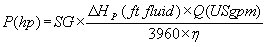
    [link Point to another website Only the registered members can access]
    Flow and total head are measured and then the efficiency can be determined.

    The efficiency is calculated for various flow rates and plotted on the same curve as the pump performance or

    [link Point to another website Only the registered members can access]

    [link Point to another website Only the registered members can access]
    Centrifugal pumps come in many designs and some are more suitable for low-flow high-head applications and others for high-flow low-head and some in between. They are designed to achieve their maximum efficiency to accommodate a particular application.

    The specific speed number gives an indication of what type of pump is more suited to your application. The effect of specific speed on pump design and how to calculate this number is

    [link Point to another website Only the registered members can access]
    It is possible to predict efficiency. Some years ago, a survey of typical industrial pumps was made. The average efficiency was plotted against the specific speed and it shows what the ultimate efficiency limits are for pumps under various operating conditions.

    [link Point to another website Only the registered members can access]
    Suction specific speed is another parameter that can affect efficiency. This number is a measure of how much flow can be put through a pump before it starts to choke (reaches it's upper flow limit) and cavitates (the pressure at the suction becomes low enough that the fluid vaporizes).

    [link Point to another website Only the registered members can access] [hr][/hr] End suction pump: a typical centrifugal pump, the workhorse of industry. Also known as volute pump, standard pump, horizontal suction pump. The back pull out design is a standard feature and allows easy removal of the impeller and shaft with the complete drive and bearing assembly while keeping the piping and motor in place.
    Some of its components are:
    [table]
    [TR]
    [TD]1.Casing, volute

    2. Impeller, vanes, vane tips, backplate, frontplate (shroud), back vanes, pressure equalising passages or balancing holes

    3. Back cover parallel to Plane of the impeller intake

    4. Stuffing Box - Gland/mechanical seal housing or packing/lantern ring

    5. Pump shaft

    6. Pump casing

    7. Bearing housing

    8. Bearings

    9. Bearing seals

    11. Back pull out

    12. Bearings
    13. Bearing seals
    [/TD]
    [TD][/TD]
    [/TR]
    [/table]


    Balancing holes

    Backvanes

    Equivalent length: a method used to establish the friction loss of fittings (see next figure). The equivalent length of the fitting can be found using the nomograph below. The equivalent length is then added to the pipe length, and with this new pipe length the overall pipe friction loss is calculated. This method is rarely used today. See

    [link Point to another website Only the registered members can access]
    [hr][/hr] Energy gradient: see

    [link Point to another website Only the registered members can access] [hr][/hr] Expeller: a hydro-dynamic seal that provides a seal without addition of water to the gland, specially useful for liquid slurries.

    (image source: Worthington Pumpworld article, see below)


    see an article on the expeller seal on this web page:

    [link Point to another website Only the registered members can access] [hr][/hr] External Gear pump: a positive displacement pump. Two spur gears are housed in one casing with close clearance. Liquid is trapped between the gear tooth spaces and the casing, the rotation of the gears pumps the liquid. They are also used for high pressure industrial transfer and metering applications on clean, filtered, lubricating fluids.


    Viking Pumps is a major supplier of these pumps

    [link Point to another website Only the registered members can access] [hr][/hr] Flat curve: head decreases very slowly as flow increases, see

    [link Point to another website Only the registered members can access] [hr][/hr] Flow splitter:

    [link Point to another website Only the registered members can access] [hr][/hr] Foot valve: a check valve that is put on the end of the pump suction pipe, often accompanied with an integrated strainer.

    [link Point to another website Only the registered members can access]
    [hr][/hr] Forum: the pumpfundamentals forum is a place where you can ask questions on centrifugal pumps and other types and also share you knowledge with others. A valuable resource.

    [link Point to another website Only the registered members can access] [hr][/hr] Friction loss (pump): the following chart shows the distribution of friction losses and their relative size that occur in a pump.

    Source: Centrifugal and Axial Flow Pumps by A.J. Stepanoff published by John Wiley and Sons 1957.
    [hr][/hr] Friction (pipe): The force produced as reaction to movement. All fluids are subject to friction when they are in motion. The higher the fluid viscosity, the higher the friction force for the same flow rate. Friction is produced internally as one layer of fluid moves with respect to another and also at the fluid wall interface. Rough pipes will also produce high friction.

    [hr][/hr] Friction head loss (pipe): the friction head loss is given by the

    [link Point to another website Only the registered members can access]

    [link Point to another website Only the registered members can access]
    Table of head loss factors for water from the Cameron Hydraulic data book.


    For

    [link Point to another website Only the registered members can access] [hr][/hr]


  8.    Spons.


  9. #6
    Friction factor f (pipe): the friction factor f is required for the calculation of the friction head loss. It is given by the

    [link Point to another website Only the registered members can access]

    [link Point to another website Only the registered members can access]

    [link Point to another website Only the registered members can access]

    [link Point to another website Only the registered members can access]
    [hr][/hr] Front plate: see

    [link Point to another website Only the registered members can access] [hr][/hr] Gland: see

    [link Point to another website Only the registered members can access] [hr][/hr] Glandless pumps: see

    [link Point to another website Only the registered members can access] [hr][/hr] Hazen-Williams equation: this equation is now rarely used but has been much used in the past and does yield good results although it has many limitations, one being that it does not consider viscosity. It therefore can only be applied to fluids with a similar viscosity to water at 60F. It has been replaced by the Darcy-Weisbach and the Colebrook equation. Interestingly the NFPA (National Fire Protection Association) mandates that the Hazen-Williams equation be used to do the friction calculations on sprinkler systems for example.

    The C coefficients use in the above Hazen-Williams equation are given in the table below.
    The source of this equation is the

    [link Point to another website Only the registered members can access]
    Hazen-Williams equation C coefficients.
    [hr][/hr] Head: the height at which a pump can displace a liquid to. Head is also a form of energy. In pump systems there are 4 different types of head: elevation head or static head, pressure head, velocity head and friction head loss. For

    [link Point to another website Only the registered members can access]
    Also known as specific energy or energy per unit weight of fluid, the unit of head is expressed in feet or meters.

    [link Point to another website Only the registered members can access]
    Try this

    [link Point to another website Only the registered members can access] [hr][/hr] Hydraulic gradient: All the energy terms of the system ( for example velocity head and piping and fitting friction loss) are converted to head and graphed above an elevation drawing of the installation. It helps to visualize where all the energy terms are located and ensure that nothing is missed.

    [hr][/hr] Impeller: The rotating element of a pump which consists of a disk with curved vanes. The impeller imparts movement and pressure to the fluid.

    See this paper on impellers by the

    [link Point to another website Only the registered members can access]

    Figure 5 Major pump parts and terminology.

    The impeller consists of a back plate, vanes and for closed impellers a front plate or shroud. It may be equipped with wear rings, back vanes and balancing holes.

    for more on the different impeller types see

    [link Point to another website Only the registered members can access] [hr][/hr] Impeller eye: that area of the centrifugal pump that channels fluid into the vane area of the impeller. The diameter of the eye will control how much fluid can get into the pump at a given flow rate without causing excessive pressure drop and cavitation. The velocity within the eye will control the NPSHR,

    [link Point to another website Only the registered members can access] see also

    [link Point to another website Only the registered members can access]
    For

    [link Point to another website Only the registered members can access] [hr][/hr] Inducer: an inducer is a device attached to the impeller eye that is usually shaped like a screw that helps increase the pressure at the impeller vane entrance and make viscous or liquids with high solids pumpable. It can also be used to reduce the NPSHR.


    (image source: The Worthington Pump Co. - Pumpworld).

    see articles on inducers on this web page:

    [link Point to another website Only the registered members can access]


  10. #7
    Internal gear pump: a positive displacement pump.
    The internal gear pumping principle was invented by Jens Nielsen, one of the founders of

    [link Point to another website Only the registered members can access]

    Viking Pumps is a major supplier of these pumps

    [link Point to another website Only the registered members can access] [hr][/hr] Jet pump: a jet pump is a commonly available residential water supply pump. It has an interesting clever design that can lift water from a well (up to 25 feet) and allow it to function without a check valve on the suction and furthermore does not require priming. The heart of the design is a

    [link Point to another website Only the registered members can access]
    see this article for

    [link Point to another website Only the registered members can access]

    [link Point to another website Only the registered members can access]

    [link Point to another website Only the registered members can access] [hr][/hr] K factor: a factor that provides the head loss for fittings. It is used with the following equation


    The K factor for various fittings can he found in many publications. As an example, Figure 6 depicts the relationship between the K factor of a 90° screwed elbow and the diameter (D). The type of fitting dictates the relationship between the friction loss and the pipe size.

    Note: this method assumes that the flow is fully turbulent (see the demarcation line on the Moody diagram of

    [link Point to another website Only the registered members can access]

    Figure 6 K factor vs. diameter of fitting (source: Hydraulic Institute Engineering data book)
    Another good source for fitting K factors is the Crane Technical Data Brochure.

    Figure 7 Values for the K factor with respect to the friction factor for a standard tee.


    The Crane technical paper gives the K value for a fitting in terms of the term fT as in this example for a standard tee.


    As is the case for the data shown in Figure 6, the friction loss for fittings is based on the assumption that the flow is highly turbulent, in fact that it is so turbulent that the Reynolds number is no longer a factor and pipe roughness is the main parameter affecting friction. This can be seen in the

    [link Point to another website Only the registered members can access]

    The term fT used by Crane is the friction factor and is the same as that given by the Colebrook or the Swamee-Jain equation.


    When the Reynolds number becomes large the value of fT (using the

    [link Point to another website Only the registered members can access]


    furthermore the

    [link Point to another website Only the registered members can access] T becomes:


    Therefore the value of the K factor is easily calculated based on the diameter of the fitting, the friction factor fT and the multiplication factor for each type of fitting.

    [hr][/hr] Laminar: A distinct flow regime that occurs at low

    [link Point to another website Only the registered members can access]

    Figure 8 Laminar flow velocity profile.
    [hr][/hr] Lobe pump: a positive displacement pump. Primarily used in food applications because they handle solids without damaging them. Lobes are driven by external timing gears as a result the lobes do not make contact. Liquid travels around the interior of the casing in the pockets between the lobes and the casing, meshing of the lobes forces liquid through the outlet port under pressure. They also offer continuous and intermittent reversible flows and can operate dry for brief periods of time. Typical applications are in following industries: food, pharmaceuticals, paper & pulp, beverages, chemical and biotechnology.


    Viking Pumps is a major supplier of these pumps

    [link Point to another website Only the registered members can access] [hr][/hr] Low NPSH pump: a pump designed for application with a low

    [link Point to another website Only the registered members can access]

    [link Point to another website Only the registered members can access] see

    [link Point to another website Only the registered members can access] [hr][/hr] Mechanical seal: a name for the joint that seals the fluid in the pump stopping it from coming out at the joint between the casing and the pump shaft. The following image (source: the Pump Handbook by McGraw-Hill) shows a typical mechanical seal. A mechanical seal is a sealing device which forms a running seal between rotating and stationary parts. They were developed to overcome the disadvantages of compression packing. Leakage can be reduced to a level meeting environmental standards of government regulating agencies and maintenance costs can be lower.

    [link Point to another website Only the registered members can access]
    [hr][/hr] Mercury (Hg): A metal that remains liquid at room temperature. This property makes it useful when used in a thin vertical glass tube since small changes in pressure can be measured as changes in the mercury column height. The inch of mercury is often used as a unit for measuring vacuum level or pressures below atmospheric pressure.


    The relationship between inches of mercury, psi and psia units of pressure.
    [hr][/hr] Minimum flow rate
    Most centrifugal pumps should not be used at a flow rate less than 50% of the B.E.P. (best efficiency point) flow rate without a recirculation line. (

    [link Point to another website Only the registered members can access] see also the

    [link Point to another website Only the registered members can access]
    How is the minimum flow of a centrifugal pump established (answer from the Hydraulic Institute

    [link Point to another website Only the registered members can access] The factors which determine minimum allowable rate of flow include the following:

    * Temperature rise of the liquid -- This is usually established as 15°F and results in a very low limit. However, if a pump operates at shut off, it could overheat badly.

    * Radial hydraulic thrust on impellers -- This is most serious with single volute pumps and, even at flow rates as high as 50% of BEP could cause reduced bearing life, excessive shaft deflection, seal failures, impeller rubbing and shaft breakage.

    * Flow re-circulation in the pump impeller -- This can also occur below 50% of BEP causing noise, vibration, cavitation and mechanical damage.

    * Total head characteristic curve - Some pump curves droop toward shut off, and some VTP curves show a dip in the curve. Operation in such regions should be avoided.


    There is no standard which establishes precise limits for minimum flow in pumps, but "ANSI/HI 9.6.3-1997 Centrifugal and Vertical Pumps - Allowable Operating Region" discusses all of the factors involved and provides recommendations for the "Preferred Operating Region".


  11. #8
    Minimum NPSHA: the margin of safety or minimum NPSHA that should be available depends in part on the amount of suction energy of the pump. The suction energy level of the pump increases with:
    • The casing suction diameter
    • The pump speed
    • The suction specific speed
    • The specific gravity of the fluid

    Anything that increases the velocity of the pump impeller eye, the rate of flow of the pump, or the specific gravity, increases the suction energy of the pump.

    The

    [link Point to another website Only the registered members can access] [table]
    [TR]
    [TD="colspan: 4"]

    Minimum NPSH Margin Ratio Guidelines NPSHA/NPSHR
    [/TD]
    [/TR]
    [TR]
    [TD][/TD]
    [TD="colspan: 3"]
    Suction energy levels
    [/TD]
    [/TR]
    [TR]
    [TD]Application[/TD]
    [TD]Low[/TD]
    [TD]Medium[/TD]
    [TD]High[/TD]
    [/TR]
    [TR]
    [TD]Petroleum[/TD]
    [TD]1.1-a[/TD]
    [TD]1.3-a[/TD]
    [TD][/TD]
    [/TR]
    [TR]
    [TD]Chemical[/TD]
    [TD]1.1-a[/TD]
    [TD]1.3-a[/TD]
    [TD][/TD]
    [/TR]
    [TR]
    [TD]Electrical power[/TD]
    [TD]1.1-a[/TD]
    [TD]1.5-a[/TD]
    [TD]2.0-a[/TD]
    [/TR]
    [TR]
    [TD]Nuclear power[/TD]
    [TD]1.5-b[/TD]
    [TD]2.-a[/TD]
    [TD]2.5-a[/TD]
    [/TR]
    [TR]
    [TD]Cooling towers[/TD]
    [TD]1.3-b[/TD]
    [TD]1.5-a[/TD]
    [TD]2.0-a[/TD]
    [/TR]
    [TR]
    [TD]Water/Waste water[/TD]
    [TD]1.1-a[/TD]
    [TD]1.3-a[/TD]
    [TD]2.0-a[/TD]
    [/TR]
    [TR]
    [TD]General industry[/TD]
    [TD]1.1-a[/TD]
    [TD]1.2-a[/TD]
    [TD][/TD]
    [/TR]
    [TR]
    [TD]Pulp and paper[/TD]
    [TD]1.1-a[/TD]
    [TD]1.3-a[/TD]
    [TD][/TD]
    [/TR]
    [TR]
    [TD]Building services[/TD]
    [TD]1.1-a[/TD]
    [TD]1.3-a[/TD]
    [TD][/TD]
    [/TR]
    [TR]
    [TD]Slurry[/TD]
    [TD]1.1-a[/TD]
    [TD][/TD]
    [TD][/TD]
    [/TR]
    [TR]
    [TD]Pipeline[/TD]
    [TD]1.3-a[/TD]
    [TD]1.7-a[/TD]
    [TD]2.0-a[/TD]
    [/TR]
    [TR]
    [TD]Water/Food[/TD]
    [TD]1.2-a[/TD]
    [TD]1.5-a[/TD]
    [TD]2.0-a[/TD]
    [/TR]
    [/table]
    "a" - or 0.6 m (2 feet) whichever is greater
    "b" - or 0.9 m (3 feet) whichever is greater
    "a" - or 1.5 m (5 feet) whichever is greater

    see articles on NPSH guidelines on this web page:

    [link Point to another website Only the registered members can access] [hr][/hr] Motor frame:NEMA (National electrical Manufacturers Association) provides standards to which electric induction motors are built. Each frame size (for example frame 254T) is built to specified dimensions. The amount of room required for the pump assembly will depend on the size and construction of the motor. It is easy to find a chart that provides the motor dimensions vs. the frame size (see following chart).


    but I looked long and hard to find a chart that provides the frame size vs. the rpm and hp, and here it is:

    [hr][/hr] Moody diagram: A graphical representation of the laminar and turbulent (Colebrook) flow equations.


    Figure 9 the Moody diagram, a graphical representation of the laminar flow equation and the Colebrook equation for the friction factor f.
    [hr][/hr] Net Positive Suction Head Available (N.P.S.H.A.): Net positive suction head available. The head or specific energy at the pump suction flange less the vapor pressure head of the fluid. see

    [link Point to another website Only the registered members can access]
    See this

    [link Point to another website Only the registered members can access] Also for those

    [link Point to another website Only the registered members can access] [hr][/hr] Net Positive Suction Head Required (N.P.S.H.R.): Net positive suction head required. The manufacturers estimate on the NPSH required for the pump at a specific flow, total head, speed and impeller diameter. This is determined my measurement. see also

    [link Point to another website Only the registered members can access]
    This next figure provides an estimate for NPSHR for centrifugal pumps (source: Centrifugal Pump Design & Application by Val.S.Labanoff and Robert R Ross, contributed by a pump forum friend, Ravi Sankar.

    You can join the centrifugal pump discussion forum at

    [link Point to another website Only the registered members can access] For a larger scale image download

    [link Point to another website Only the registered members can access]


  12. #9
    Newtonian fluid: A fluid whose viscosity is constant and independent of the rate of shear (strain). For Newtonian fluids, there is a linear relationship between the rate of shear and the tangential stress between layers. For more information see

    [link Point to another website Only the registered members can access]
    Figure 10 Shear/strain relationship for a Newtonian fluid.

    If you want to understand what a non-Newtonian fluid feels like and what it means for viscosity to change with the rate of shear, try this experiment.

    In a large shallow bowl make a solution of approximately 1 part water and 2 parts corn starch, try moving this fluid rapidly around with your fingers. When the fingers are moved slowly, the solution behaves as expected, offering little resistance. The faster you try to move through the fluid, the higher the resistance. At that rate of shear, the solution almost behaves as a solid, If you move your fingers fast enough they will skip over the surface. This is what is meant by viscosity being dependent on rate of shear. Compare this behavior to that of molasses; you will find that even though molasses is viscous its viscosity changes very little with the shear rate. Molasses flows readily no matter how fast the movement.
    See a

    [link Point to another website Only the registered members can access] [hr][/hr] Operating point: The point (flow rate and total head) at which the pump operates. It is located at the intersection of the

    [link Point to another website Only the registered members can access]

    Figure 11 Operating point on a pump performance curve.
    [hr][/hr] Packing: see

    [link Point to another website Only the registered members can access] [hr][/hr] Partial emission pump: see

    [link Point to another website Only the registered members can access] [hr][/hr] Peripheral pump: also known as regenerative or regenerative turbine pump. These are low capacity (150 gpm or 34 m3/h) high head (5400 ft or 1645 m) pumps. The impeller has short vanes at the periphery and these vanes pass through an annular channel. The fluid enters between two impeller vanes and is set into a circular motion, this adds energy to the fluid particles which travel in a spiral like path from the inlet to the outlet. Each set of vanes continuously adds energy to the fluid particles.
    Peripheral pumps are more efficient at these low flow high head conditions than centrifugal pumps, they also require much less NPSHA than an equivalent centrifugal pump. They can also handle liquids with up to 20% entrained gases.

    They are used in a wide range of domestic and industrial applications.
    [table]
    [TR]
    [TD][/TD]
    [TD][/TD]
    [/TR]
    [/table]

    For a good explanation of the principal of operation see this

    [link Point to another website Only the registered members can access] and also from the

    [link Point to another website Only the registered members can access]
    see also

    [link Point to another website Only the registered members can access] [hr][/hr] Performance curve: A plot of Total Head vs. flow for a specific pump model, impeller diameter and speed (syn characteristic curve, water performance curve).

    [link Point to another website Only the registered members can access]
    For

    [link Point to another website Only the registered members can access]


  13. #10
    Pipe roughness: A measurement of the average height of peaks producing roughness on the internal surface of pipes. Roughness is measured in many locations and then averaged, it is usually defined in micro-inches RMS (root mean square).

    [link Point to another website Only the registered members can access]
    [hr][/hr] Piping pressure (maximum): it may be necessary in certain applications to check the maximum rating of your pipes to avoid bursting due to excessive pressure. The ASME pressure piping code B31.3 provides the maximum stress for pipes of various materials. Also the pipe flange rating will have to be checked.
    for more information see

    [link Point to another website Only the registered members can access]
    Table of allowable piping stress from the ASME pressure piping code B31.3
    [hr][/hr] Pitot pump: also know as rotating casing pump. This pump’s specialty is low to medium flow rates at high pressures. It is frequently used for high pressure shower supply on paper machines.

    Pitot (Roto-jet ) pump
    see

    [link Point to another website Only the registered members can access] see also

    [link Point to another website Only the registered members can access] [hr][/hr] Pressure: The application of a force to a body producing more or less compression within the liquid. In a static fluid pressure varies with height.
    Fluid weight is the cause of hydrostatic pressure. A thin slice of fluid is isolated so that the forces surrounding it can be visualized. If we make the slice very thin, the pressure at the top and bottom of the slice will be the same. The slice is compressed top and bottom by force vectors opposing each other. The fluid in the slice also exerts pressure in the horizontal direction against the pipe walls. These forces are balanced by stress within the pipe wall. The pressure at the bottom of the slice will be equal to the weight of fluid above it divided by the area.


    The weight of a fluid column of height (z) is:

    The pressure (p) is equal to the fluid weight (F) divided by the cross-sectional area (A) at the point where the pressure is calculated :

    where F : force due to fluid weight

    V : volume

    g : acceleration due to gravity (32.17 ft/s2)

    : fluid density in pound mass per unit volume

    : fluid density or specific weight in pound force per unit volume
    [hr][/hr] Pressure head: an expression of energy, specifically it is energy per unit weight of fluid displaced.

    [link Point to another website Only the registered members can access] We often need to calculate the pressure head that corresponds to the pressure. Pressure can be converted to pressure head or fluid column height for any fluid. However, not all fluids have the same density. Water for example has a density of 62.34 pounds per cubic foot whereas gasoline has a density of 46.75 pounds per cubic foot.

    [link Point to another website Only the registered members can access]

    where is the fluid density and is water density at standard conditions. Since

    where is the fluid density in terms of weight per unit volume. The constant gc is required to provide a relationship between mass in lbm and force in lbf .


    The quantity ( = 62.34 lbm/ft3 for water at 60 °F) is:


    After simplification, the relationship between the fluid column height and the pressure at the bottom of the column is:


  14. #11
    s the Suction Inlet under pressure or by gravity and as the ROTOR 1 turns within the flexible rubber STATOR 2 forming tightly sealed cavities 3 which moves the Liquid toward the Discharge Outlet. Pumping action starts the instant the ROTOR turns. Liquid acts as the lubricant between the pumping elements.
    [hr][/hr] Pseudoplastic: The property of a fluid whose viscosity increases slowly with rate of shear.

    For more information see

    [link Point to another website Only the registered members can access] [hr][/hr] Pumps as turbines (PAT): Pumps used in reverse to act as turbines.

    For more information see

    [link Point to another website Only the registered members can access]

    [link Point to another website Only the registered members can access] Radial flow pump: refers to the design of a centrifugal pump for medium head and medium flow or high head and low flow. The value of the

    [link Point to another website Only the registered members can access]

    [link Point to another website Only the registered members can access] [hr][/hr] Radial vane pump: also known as partial emission pump or vane pump. A frame mounted, end suction, top centerline discharge, ANSI pump designed specifically to handle corrosive chemicals at low flows.

    Vane pump
    see

    [link Point to another website Only the registered members can access] see also

    [link Point to another website Only the registered members can access] [hr][/hr] Recessed impeller pump: sometimes known as vortex pump. This is a frame-mounted, back pull-out, end suction, recessed impeller, tangential discharge pump designed specifically to handle certain bulky or fibrous solids, air or gas entrained liquids or shear sensitive liquids.

    Recessed impeller pump
    see

    [link Point to another website Only the registered members can access]
    see also

    [link Point to another website Only the registered members can access] [hr][/hr] Recirculation: at low flow and high flow compared to the flow at the B.E.P. the fluid will start to recirculate or move in a reverse direction at the suction and at the discharge.

    It is well established that cavitation type of damage seen on the inlet vanes and not associated with inadequate NPSH can be directly linked to the pump operating in the suction recirculation zone. Similar damage seen on the discharge vane tips can also be associated with pump operation in the discharge recirculation zone.

    The suction and discharge recirculation may occur at different points as shown on the characteristic curve below.


    [hr][/hr] Regenerative pump: see

    [link Point to another website Only the registered members can access] [hr][/hr] Reynolds number: the Reynolds number is proportional to the ratio of velocity and viscosity, the higher the number (higher than 4000 for turbulent flow) the more turbulent the flow and the less

    [link Point to another website Only the registered members can access]

    [link Point to another website Only the registered members can access]

    [link Point to another website Only the registered members can access]
    [hr][/hr] Rheopectic: The property of a fluid whose viscosity increases with time.

    For more information see

    [link Point to another website Only the registered members can access] [hr][/hr] Rubber pump liner: see

    [link Point to another website Only the registered members can access] [hr][/hr] Screw impeller: The screw centrifugal impeller is shaped like a tapered Archimedes screw. Originally developped for pumping live fish, the screw centrifugal pump has become popular for
    many solids handling applications.

    for more information see

    [link Point to another website Only the registered members can access] see also

    [link Point to another website Only the registered members can access] [hr][/hr] Sealless pump: see

    [link Point to another website Only the registered members can access]


  15.    Spons.


  16. #12
    see

    [link Point to another website Only the registered members can access] [hr][/hr] Shroud: see

    [link Point to another website Only the registered members can access] [hr][/hr] Shut-off head: The Total Head corresponding to zero flow on the pump performance curve.


    Figure 12 Shut-off head and other points on a centrifugal pump performance curve.
    The shut-off head is the Total Head that the pump can deliver at zero flow (see next Figure). The shut-off head is important for 2 reasons.


    1. In certain systems (admittedly unusual), the pump discharge line may have to run at a much higher elevation than the final discharge point. The fluid must first reach the higher elevation in the system. If the shut-off head is smaller than the static head corresponding to the high point, then flow will not be established in the system.


    2. During start-up and checkout of the pump, a quick way to determine if the pump has the potential capacity to deliver the head and flow required, is to measure the shut-off head. This value can be compared to the shut-off head predicted by the performance curve of the pump.


    [hr][/hr] Side channel pump: is a pump that provides high head at low flows with the added benefit of being able to handle gases. The principle of the pump is well explained on the

    [link Point to another website Only the registered members can access]

    [link Point to another website Only the registered members can access]

    [link Point to another website Only the registered members can access]


    You will find other examples and suppliers of side channel pumps in the

    [link Point to another website Only the registered members can access] [hr][/hr] Siphon: A system of piping or tubing where the exit point is lower than the entry point and where some part of the piping is above the free surface of the fluid source.


    Figure 14 A siphon.
    See this article for

    [link Point to another website Only the registered members can access]
    [hr][/hr] Sludge pump: certain types of sludges tend to settle very quickly and are hard to keep in suspension. The Lawrence pump company has solved this problem by putting an agitator in front of the pump suction.

    Sludge pump
    see

    [link Point to another website Only the registered members can access] [hr][/hr] Slurry pump: a rugged heavy duty pump intended for aggressive or abrasive slurry solutions typically found in the mining industry with particles of various sizes. It achieves this by lining the inside of the pump casing as well as the impeller with rubber.

    Slurry pump
    see

    [link Point to another website Only the registered members can access]
    and also

    [link Point to another website Only the registered members can access]
    [hr][/hr] Specific gravity (SG): the ratio of the density of a fluid to that of water at standard conditions. If the SG is 1 then the density is the same as water, if it is less than 1 then the fluid is less dense than water and heavier than water if the SG is bigger than 1. Mercury has an SG of 14, gasoline has an SG of 0.8. The usefulness of specific gravity is that it has no units since it is a comparative measure of density or a ratio of densities therefore specific gravity will have the same value no matter what system of units we are using, Imperial or metric.
    For more information see

    [link Point to another website Only the registered members can access]
    See this

    [link Point to another website Only the registered members can access]
    the above image is from the Cameron Hydraulic data book which contains a great deal of information on fluid properties. To purchase go to the

    [link Point to another website Only the registered members can access] [hr][/hr] Specific speed: a number that provides an indication what type of pump (for example radial, mixed flow or axial) is suitable for the application. The figure below is know as the Balje diagram.

    Specific speed is calculated with this formula:


    The conversion from metric to imperial specific speed NSm is given below:


    see also

    [link Point to another website Only the registered members can access] for an article on this topic see

    [link Point to another website Only the registered members can access] and here is a

    [link Point to another website Only the registered members can access]
    [hr][/hr] Standard volute pump close coupled: The volute is the casing which has a spiral shape. The motor shaft is connected to the impeller without an intermediate coupling providing a compact arrangement. The flow range is typically less than 300 gpm.

    The picture for this pump is provided courtesy of

    [link Point to another website Only the registered members can access] [hr][/hr] Standard volute pump separately coupled: The volute is the casing which has a spiral shape. The motor shaft is connected to the impeller with an intermediate shaft with two couplings.

    The picture for this pump is provided courtesy of

    [link Point to another website Only the registered members can access] [hr][/hr] Strain: The ratio between the absolute displacement of a reference point within a body to a characteristic length of the body.

    [link Point to another website Only the registered members can access]


  •   

Similar Threads

  1. Piping System Curve for one pump vs two pump in AFT Fathom
    By roman_maximo in forum Pipeline And Fluid Flow
    Replies: 0
    Last Post: 08-27-2013, 07:02 AM
  2. Centrifugal pump system tutorial
    By Esam in forum Mechanical Engineering
    Replies: 3
    Last Post: 03-11-2013, 01:21 AM
  3. Centrifugal pump system tutorial 2
    By Esam in forum Mechanical Engineering
    Replies: 0
    Last Post: 08-08-2011, 07:23 AM
  4. Electrical Submersible Pump System Handbook
    By rodstring in forum Oil And Gas Process
    Replies: 5
    Last Post: 10-30-2010, 06:05 AM
  5. Replies: 0
    Last Post: 06-25-2010, 01:56 PM

Tags for this Thread

Bookmarks

Posting Permissions

  • You may not post new threads
  • You may not post replies
  • You may not post attachments
  • You may not edit your posts
  •