


CENTRIFUGAL PUMP SYSTEM TUTORIAL 1
What is total head
Total head and flow are the main criteria that are used to compare one pump with another or to select a centrifugal pump for an application. Total head is related to the discharge pressure of the pump. Why can't we just use discharge pressure? Pressure is a familiar concept, we are familiar with it in our daily lives. For example, fire extinguishers are pressurized at 60 psig (413 kPa), we put 35 psig (241 kPa) air pressure in our bicycle and car tires.For good reasons, pump manufacturers do not use discharge pressure as a criteria for pump selection. One of the reasons is that they do not know how you will use the pump. They do not know what flow rate you require and the flow rate of a centrifugal pump is not fixed. The discharge pressure depends on the pressure available on the suction side of the pump. If the source of water for the pump is below or above the pump suction, for the same flow rate you will get a different discharge pressure. Therefore to eliminate this problem, it is preferable to use the difference in pressure between the inlet and outlet of the pump.
The manufacturers have taken this a step further, the amount of pressure that a pump can produce will depend on the density of the fluid, for a salt water solution which is denser than pure water, the pressure will be higher for the same flow rate. Once again, the manufacturer doesn't know what type of fluid is in your system, so that a criteria that does not depend on density is very useful. There is such a criteria and it is called TOTAL HEAD, and it is defined as the difference in head between the inlet and outlet of the pump.
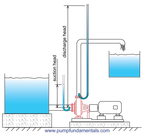
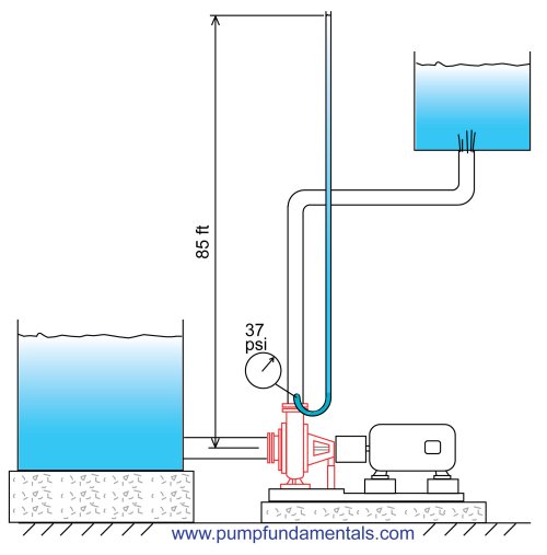
You can measure the discharge head by attaching a tube to the discharge side of the pump and measuring the height of the liquid in the tube with respect to the suction of the pump. The tube will have to be quite high for a typical domestic pump. If the discharge pressure is 40 psi the tube would have to be 92 feet high. This is not a practical method but it helps explain how head relates to total head and how head relates to pressure. You do the same to measure the suction head. The difference between the two is the total head of the pump.
Figure 25
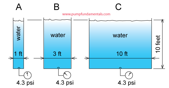
The fluid in the measuring tube of the discharge or suction side of the pump will rise to the same height for all fluids regardless of the density. This is a rather astonishing statement, here's why. The pump doesn’t know anything about head, head is a concept we use to make our life easier. The pump produces pressure and the difference in pressure across the pump is the amount of pressure energy available to the system. If the fluid is dense, such as a salt solution for example, more pressure will be produced at the pump discharge than if the fluid were pure water. Compare two tanks with the same cylindrical shape, the same volume and liquid level, the tank with the denser fluid will have a higher pressure at the bottom. But the static head of the fluid surface with respect to the bottom is the same. Total head behaves the same way as static head, even if the fluid is denser the total head as compared to a less dense fluid such as pure water will be the same. This is a surprising fact, see this .
For these reasons the pump manufacturers have chosen total head as the main parameter that describes the pump’s available energy.
What is the relationship between head and total head?
Total head is the height that the liquid is raised to at the discharge side of the pump less the height that it is raised to at the suction side (see Figure 25). Why less the height at the suction side? Because we want the energy contribution of the pump only and not the energy that is supplied to it.
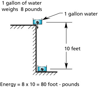
What is the unit of head? First let's deal with the unit of energy. Energy can be expressed in foot-pounds which is the amount of force required to lift an object up multiplied by the vertical distance. A good example is weight lifting. If you lift 100 pounds (445 Newtons) up 6 feet (1.83 m), the energy required is 6 x 100= 600 ft-lbf (814 N-m).
Head is defined as energy divided by the weight of the object displaced. For the weight lifter, the energy divided by the weight displaced is 6 x 100 / 100= 6 feet (1.83 m), so the amount of energy per pound of dumbbell that the weight lifter needs to provide is 6 feet. This is not terribly useful to know for a weight lifter but we will see how very useful it is for displacing fluids.
Figure 26
You may be interested to know that 324 foot-pounds of energy is equivalent to 1 calorie. This means that our weight lifter spends 600/324 = 1.8 calories each time he lifts that weight up 6 feet, not much is it.
[hr][/hr] The following figure shows how much energy is required to displace vertically one gallon of water.
Figure 27
[hr][/hr] This next figure shows how much head is required to do the same job.
Figure 28
[hr][/hr] If we use energy to describe how much work the pump needs to do to displace a volume of liquid we need to know the weight. If we use head, we only need to know the vertical distance of movement. This is very useful for fluids because pumping is a continuous process, usually when you pump you leave the pump turned on, you don't start and stop the pump for every pound of fluid displaced. We are mainly interested in establishing a continuous flow rate.
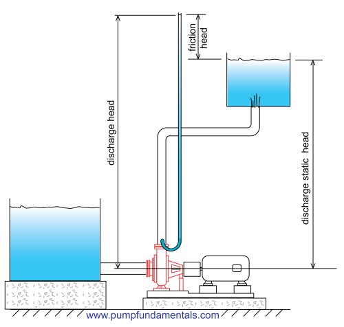
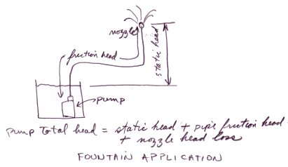
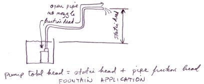
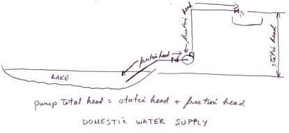
The other very useful aspect of using head is that the elevation difference or static head can be used as one part of the value of total head, the other part being friction head as shown in this next figure.
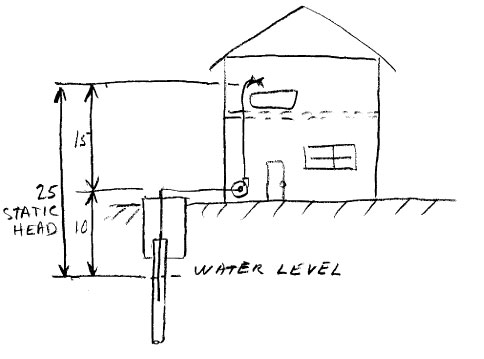
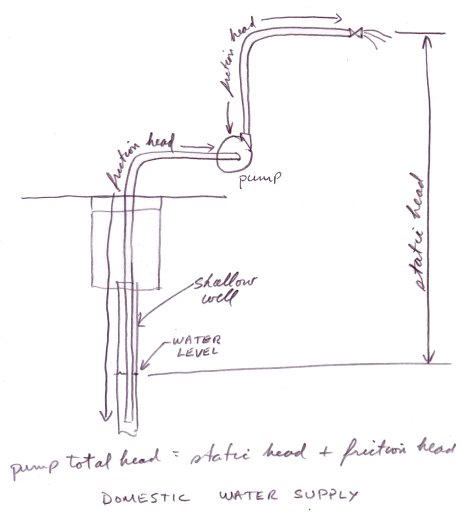
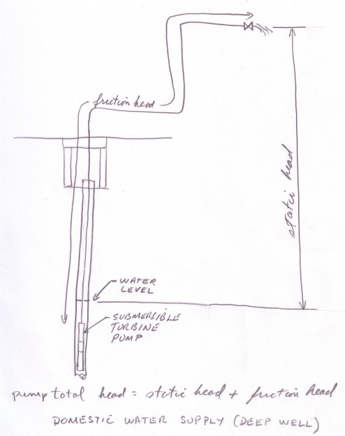
How much static head is required to pump water up from the ground floor to the second floor, or 15 feet up? Remember that you must also take into consideration the level of the water in the suction tank. If the water level is 10 feet below the pump suction connection then the static head will be 10 + 15 = 25 feet. Therefore the total head will have to be at least 25 feet plus the friction head loss of the fluid moving through the pipes.
Figure 29
[hr][/hr] How to determine friction head
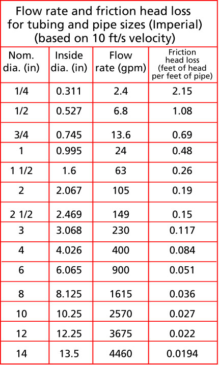
Friction head is the amount of energy loss due to friction of the fluid moving through pipes and fittings. It takes a force to move the fluid against friction, in the same way that a force is required to lift a weight. The force is exerted in the same direction as the moving liquid and energy is expended. In the same way that head was calculated to lift a certain weight, the friction head is calculated with the force required to overcome friction times the displacement (pipe length) divided by the weight of fluid displaced. These calculations have been done for us and you can find the values for friction head loss in Table 1 for different pipe sizes and flow rates.
Table 1
Download a printer friendly version ([link Point to another website Only the registered members can access]
[link Point to another website Only the registered members can access]
Table 1 gives the flow rate and the friction head loss for water being moved through a pipe at a typical velocity of 10 ft /s. I have chosen 10 ft/s as a target velocity because it is not too large which would create allot of friction and not too small which would slow things down. If the velocity is less, then the friction loss will be less and if the velocity is higher the loss will be greater than is shown in Table 1. For the suction side of the pump, it is desirable to be more conservative and size pipes for a lower velocity, for example between 4 and 7 feet/second. This is why you normally see a bigger pipe size on the suction side of the pump than on the discharge. A rule of thumb is to make the suction pipe the same size or one size larger than the suction connection.
Why bother with velocity, isn’t flow rate enough information to describe fluid movement through a system. It depends how complicated your system is, if the discharge pipe has a constant diameter then the velocity though out will be the same. Then if you know the flow rate, based on the friction loss tables, you can calculate the friction loss with the flow rate only. If the discharge pipe diameter changes then the velocity will change for the same flow rate and a higher or lower velocity means a higher or lower friction loss in that portion of the system.You will then have to use the velocity to calculate the friction head loss in this part of the pipe.
If you would like to see a chart of flow rates for 5 ft/s ([link Point to another website Only the registered members can access]
or [link Point to another website Only the registered members can access]
[link Point to another website Only the registered members can access]
[link Point to another website Only the registered members can access]
For those of you who would like to do your own velocity calculations, you can[link Point to another website Only the registered members can access]
Those who would like to do pipe friction calculations can[link Point to another website Only the registered members can access]
[hr][/hr] The performance or characteristic curve of the pump
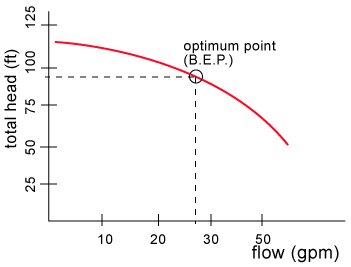
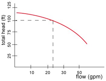
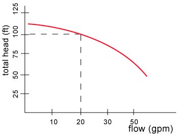
The pump characteristic curve has a similar appearance to the previous curve shown that I also called a characteristic curve that showed the relationship between discharge pressure vs. flow (see Figure 21). As I mentioned this is not a practical way of describing the performance because you would have to know the suction pressure used to generate the curve. Figure 30 shows a typical total head vs. flow rate characteristic curve. This is the type of curve that all pump manufacturers publish for each model pump for a given operating speed.
Not all manufacturer's will provide you with the pump characteristic curve. However, the curve does exist and if you insist you can probably get it. Generally speaking the more you pay, the more technical information you get.
Figure 30
[hr][/hr] How to select a centrifugal pump
It is unlikely that a centrifugal pump, bought off the shelf, will satisfy exactly your flow requirement. The flow rate that you obtain depends on the physical characteristics of your system such as friction which depends on the length and size of the pipes and elevation difference which depends on the building and location. The pump manufacturer has no means of knowing what these constraints will be. This is why buying a centrifugal pump is more complicated than buying a positive displacement pump which will provide its rated flow no matter what system you install it in.
The main factors that affect the flow rate of a centrifugal pump are:
- friction, which depends on the length of pipe and the diameter
- static head, which depends on the difference of the pipe end discharge height vs. the suction tank fluid surface height
- fluid viscosity, if the fluid is different than water.
The steps to follow to select a centrifugal pump are:
1. Determine the flow rate
To size and select a centrifugal pump, first determine the flow rate. If you are a home owner, find out which of your uses for water is the biggest consumer. In many cases, this will be the bathtub which requires approximately 10 gpm (0.6 L/s). In an industrial setting, the flow rate will often depend on the production level of the plant. Selecting the right flow rate may be as simple as determining that it takes 100 gpm (6.3 L/s) to fill a tank in a reasonable amount of time or the flow rate may depend on some interaction between processes that needs to be carefully analyzed.
2. Determine the static head
This a matter of taking measurements of the height between the suction tank fluid surface and the discharge pipe end height or the discharge tank fluid surface elevation.
3. Determine the friction head
The friction head depends on the flow rate, the pipe size and the pipe length. This is calculated from the values in the tables presented here (see Table 1). For fluids different than water the viscosity will be an important factor and Table 1 is not applicable.
4. Calculate the total head
The total head is the sum of the static head (remember that the static head can be positive or negative) and the friction head.
5. Select the pump
You can select the pump based on the pump manufacturer’s catalogue information using the total head and flow required as well as suitability to the application.
Example of total head calculation
Example 1 - Sizing a pump for a home owner application
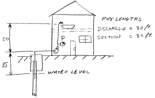
Experience tells me that to fill a bath up in a reasonable amount of time, a flow rate of 10 gpm is required. According to Table 1, the copper tubing size should be somewhere between 1/2" and 3/4", I choose 3/4". I will design my system so that from the pump there is a 3/4" copper tube main distributor, there will be a 3/4" take-off from this distributor on the ground floor to the second floor level where the bath is located. On the suction, I will use a pipe diameter of 1”, the suction pipe is 30 ft long (see Figure 30).
Figure 31
Friction loss on the suction side of the pump
According to calculation or the use of tables which is not presented here the friction loss for a 1" tube is has a friction loss of 0.068 feet per feet of pipe. In this case, the distance is 30 feet. The friction loss in feet is then 30 x 0.068 = 2.4 feet. There is some friction loss in the fittings, let's assume that a conservative estimate is 30% of the pipe friction head loss, the fittings friction head loss is = 0.3 x 2.4 = 0.7 feet. If there is a check valve on the suction line the friction loss of the check valve will have to be added to the friction loss of the pipe. A typical value of friction loss for a check valve is 5 feet. A jet pump does not require a check valve therefore I will assume there is no check valve on the suction of this system. The total friction loss for the suction side is then 2.4 + 0.7 = 3.1 feet.
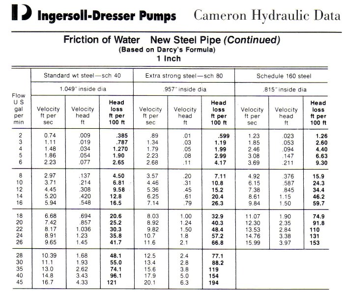
You can find the friction loss for a 1” pipe at 10 gpm in the Cameron Hydraulic data book of which the next figure is an extract:
Friction loss on the discharge side of the pump
According to calculation or the use of tables which is not presented here the friction loss for a 3/4" tube is has a friction loss of 0.23 feet per feet of pipe. In this case, the distances are 10 feet of run on the main distributor and another 20 feet off of the main distributor up to the bath, for a total length of 30 feet. The friction loss in feet is then 30 x 0.23 = 6.9 feet. There is some friction loss in the fittings, let's assume that a conservative estimate is 30% of the pipe friction head loss, the fittings friction head loss is = 0.3 x 6.9 = 2.1 feet. The total friction loss for the discharge side is then 6.9 + 2.1 = 9 feet.
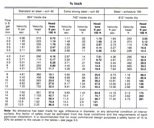
You can find the friction loss for a 0.75” pipe at 10 gpm in the Cameron Hydraulic data book of which the next figure is an extract:
The total friction loss for piping in the system is then 9 + 3.1 = 12.1 feet.
The static head as per Figure 41 is 35 feet. Therefore the total head is 35 + 12.1 = 47 feet. We can now go to the store and purchase a pump with at least 47 feet of total head at 10 gpm. Sometimes total head is called Total Dynamic Head (T.D.H.), it has the same meaning. The pump’s rating should be as close as possible to these two figures without splitting hairs. As a guideline, allow a variation of plus or minus 15% on total head. On the flow, you can also allow a variation but you may wind up paying for more than what you need.
For those of you who would like to do your own fittings friction calculation,[link Point to another website Only the registered members can access]
What is the pump rating? The manufacturer will rate the pump at its optimum total head and flow, this point is also known as the best efficiency point or B.E.P.. At that flow rate, the pump is at its most efficient and there will be minimal amount of vibration and noise. Of course, the pump can operate at other flow rates, higher or lower than the rating but the life of the pump will suffer if you operate too far away from its normal rating. Therefore, as a guideline aim for a maximum variation of plus or minus 15% on total head.


 Reply With Quote
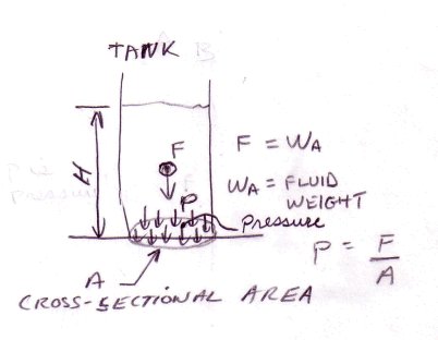


 We can measure head at the discharge side of the pump by connecting a tube and measuring the height of liquid in the tube.Since the tube is really only a narrow tank we can use the pressure vs. tank height equation
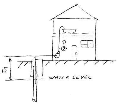

Bookmarks