


The CYMGRD software is a substation grounding grid design and analysis program specially developed to help engineers optimize the design of new grids and reinforce existing grids* of any shape* by virtue of easy to use* built-in danger point evaluation facilities. User-friendly data entry* efficient analysis algorithms and powerful graphical facilities make the CYMGRD software an efficient tool which helps engineers arrive at technically sound and economical designs.
New Release - CYMGRD 7.0 combines industry-led features and engineering know-how to deliver a solution for the safe and optimal design of new grids and the reinforcement of existing grids.
CYMGRD 7.0 offers a wide range of enhanced capabilities and new functionalities:
International safety standards are now supported
Data entry based on the Schlumburger-Palmer Measurement method
Multiple Soil Measurement Axes
Complete global report of all analysis
[link Point to another website Only the registered members can access]
The CYMGRD software is a substation grounding grid design and analysis program specially developed to help engineers optimize the design of new grids and reinforce existing grids* of any shape* by virtue of easy to use* built-in danger point evaluation facilities.
User-friendly data entry* efficient analysis algorithms and powerful graphical facilities make the CYMGRD software an efficient tool that helps the engineer arrive at technically sound and economical designs.
Program Features
The use of the CYMGRD software allows for the rapid analysis of various design alternatives to choose an economical solution for any particular installation.
The program conforms to IEEE 80™ 2000* IEEE 81™ 1983 and IEEE 837™ 2002.
Analytical Capabilities
Finite element analysis of the ground grid conductors and rods
Computation of the station ground resistance (Rg) and the Ground Potential Rise (GPR)
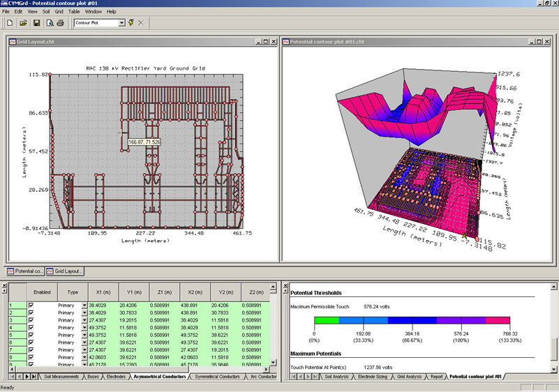
Touch and surface potential analysis* inside and outside the grid perimeter* with color display in 2D or 3D representation
Step voltage analysis
Uniform or two-layer soil model from field measurements or user-defined values
Computation of reduction factor (Cs)
Library of the most common types of surface layer materials
Library of typical station soil resistivity values
Safety assessment calculations for maximum permissible touch and step voltages as per IEEE 80™ 2000
Current Split Factor (SF) estimated from substation configuration data as per IEEE 80™ 2000
Computation of the Decrement Factor (DF) from bus (X/R) ratio and shock duration data as per IEEE 80™ 2000
DC component of asymmetrical fault current taken into account in the computations
Electrode analysis for the optimal sizing of conductors and rods based on the most common type of electrode material as per IEEE Std. 80-2000 and Std. 837-2002
Supports symmetrical or asymmetrical grids of any shape
Arbitrarily located ground rods
Ability to model return electrodes and distinct electrodes
Ability to model concrete encased rods
Computation of maximum single phase to ground fault current for a specified grid
The CYMGRD/AutoCAD® Interface module
The CYMGRD / AutoCAD® Interface module allows the user to alternate between the AutoCAD® and the CYMGRD environments.
This utility is not a substitute for AutoCAD®. In fact* AutoCAD® remains a firm software requirement for CADGRD* because it is AutoCAD® that will produce the necessary *.DXF or *.DWG file(s) that contain the pictorial description of the substation grid layout realized with the CYMGRD software.
Simulation Results Management
The charts functionality allows:
Graphical comparison of deduced soil model with field measurements* for model acceptance
Color-coding of the surface potential gradients based on user-defined thresholds for touch or surface potentials. Any area of the grid can be selected with the mouse for detailed calculations and danger point evaluation
Equipotential contours for surface potentials in either 2-D or 3-D plots* with facilities to examine the graphs from any desired viewing angle
Graphics of touch and step voltage variation along any straight line* with comparison to the safe values computed by the safety assessment module
Graphic indications on the 2-D grid layout of the area being analyzed for touch and step voltages* for easy identification of hazardous locations


 Reply With Quote

Bookmarks