


[h=CENTRIFUGAL PUMP SYSTEMS TIPS]1[/h]
This is a list of ideas or DOS AND DON'TS for pump systems. You may not of thought of some of these and they will help you design and trouble-shoot pump systems and select the proper pump. Also there is information here that is hard to find elsewhere. You can think of this list as GUIDELINES for the pump system designer.
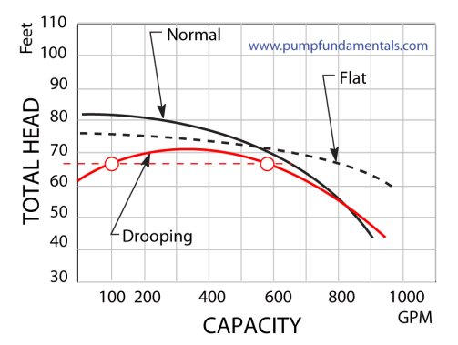
1. Flow and pressure relationship of a pump
When the flow increases, the discharge pressure of the pump decreases, and when the flow decreases the discharge pressure increases
2. Do not let a pump run at zero flow
Do not let a centrifugal pump operate for long periods of time at zero flow. In residential systems, the pressure switch shuts the pump down when the pressure is high which means there is low or no flow.
3. Use pressure gauges
Make sure your pump has a pressure gauge on the discharge side close to the outlet of the pump this will help you diagnose pump system problems. It is also useful to have a pressure gauge on the suction side, the difference in pressure is proportional to the total head. The pressure gauge reading will have to be corrected for elevation since the reference plane for total head calculation is the suction flange of the pump.
4. Do not let a pump run dry, use a check valve
Most centrifugal pumps cannot run dry, ensure that the pump is always full of liquid. In residential systems, to ensure that the pump stays full of the liquid use a check valve (also called afoot valve) at the water source end of the suction line. Certain types of centrifugal pumps do not require a check valve as they can generate suction at the pump inlet to lift the fluid into the pump, see
[link Point to another website Only the registered members can access]
Make use of check valves to isolate pumps installed in parallel.
5. Suction valves
Gate valves at the pump suction and discharge should be used as these offer no resistance to flow and can provide a tight shut-off. Butterfly valves are often used but they do provide some resistance and their presence in the flow stream can potentially be a source of hang-ups which would be critical at the suction. They do close faster than gate valves but are not as leak proof.
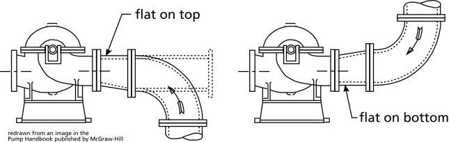
6. Eccentric reducer
Always use an eccentric reducer at the pump suction when a pipe size transition is required. Put the flat on top when the fluid is coming from below or straight (see next Figure) and the flat on the bottom when the fluid is coming from the top. This will avoid an air pocket at the pump suction and allow air to be evacuated.
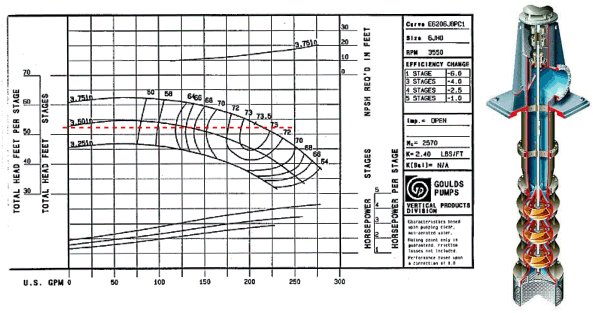
7. Use a multi-stage turbine pump for deep wells
For deep wells (200-300 feet) a submersible multi-stage pump is required. They come in different sizes (4" and 6") and fit inside your bore hole pipe. Pumps with different ratings are available, see[link Point to another website Only the registered members can access]
8. Flow control
If you need to control the flow, use a valve on the discharge side of the pump, never use a valve on the suction side for this purpose.
This is an excellent treatment of the types of control systems for a centrifugal pump. Thanks to Walter ******** of Colt Engineering a consulting engineering firm for the petro-chemical industry in Alberta, Canada.
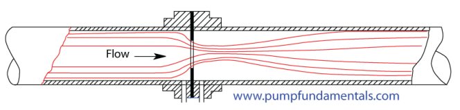
9. Plan ahead for flow meters
For new systems that do not have a flow meter, install flanges that are designed for an orifice plate in a straight part of the pipe (see next Figure) and do not install the orifice plate. In the future, whoever trouble-shoots the pump will have a way to measure flow without the owner having to incur major downtime or expense. Note: orifice plates are not suitable for slurries.
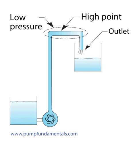
10. Avoid pockets and high points
Avoid pockets or high point where air can accumulate in the discharge piping. An ideal pipe run is one where the piping gradually slopes up from the pump to the outlet. This will ensure that any air in the discharge side of the pump can be evacuated to the outlet.
11. Location of control valves
Position control valves closer to the pump discharge outlet than the system outlet. This will ensure positive pressure at the valve inlet and therefore reduce the risk of cavitation.
When the valve must be located at the outlet such as the feed to a tank, bring the end of the pipe to the bottom of the tank and put the valve close to that point to provide some pressure on the discharge side of the valve making it easier to size the valve, extending it's life and reducing the possibility of cavitation.
12. Water hammer
Be aware of potential water hammer problems. This is particularly serious for large piping systems such as are installed in municipal water supply distribution systems. These systems are characterized by long gradually upward sloping and then downward sloping pipes. Solutions to this can involve special pressure/vacuum reducing valves at the high and low points or additional tanks which provide a buffer for pressure surges (see[link Point to another website Only the registered members can access]
For pumps 500 gals/min or larger use semi-automatic manual valves at the discharge that are controlled to open gradually when starting the pump. This will avoid water hammer during the initial start and damage to the piping system.
13. The right pipe size
The right pipe size is a compromise between cost (bigger pipes are more expensive) and excessive friction loss (small pipes cause high friction loss and will affect the pump performance). Generally speaking, the discharge pipe size can be the same size as the pump discharge connection, you can see if this is reasonable by calculating the friction loss of the whole system. For the suction side, you can also use the same size pipe as the pump suction connection, often one size bigger is used . A typical velocity range used for sizing pipes on the discharge side of the pump is 9-12 ft/s and for the suction side 3-6 ft/s.
A small pipe will initially cost less but the friction loss will be higher and the pump energy cost will be greater. If you know the cost of energy and the purchase and installation cost of the pipe you can select the pipe diameter based on a comparison of the pipe cost vs power consumption,
14. Pressure at high point of system
Calculate the level of pressure of the high point in your system. The pressure may be low enough for the fluid to vaporize and create a vapor pocket which will be detrimental to the performance of the system. The pressure at this point can be increased by installing a valve at some point past the high point and by closing this valve you can adjust the pressure at the high point. Of course, you will need to take that into account in the total head calculations of the pump.
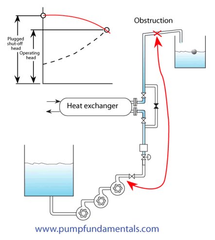
15. Pump pressure rating and series operation
For series pump installations make sure that the pressure rating of the pumps is adequate. This is particularly critical in the case where the system could become plugged due to an obstruction. All the pumps will reach their shut-of head and the pressure produced will be cumulative. The same applies for the pressure rating of the pipes and flanges.
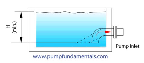
16. Inadequate pump suction submersion
There is a minimum height to be respected between the free surface of the pump suction tank and the pump suction. If this height is not maintained a vortex will form at the surface and cause air to be entrained in the pump reducing the pump capacity.
17. Pump selection
Select your pump based on total head (not discharge pressure) and flow rate. The flow rate will depend on your maximum requirement. Total head is the amount of energy that the pump needs to deliver to account for the elevation difference and friction loss in your system
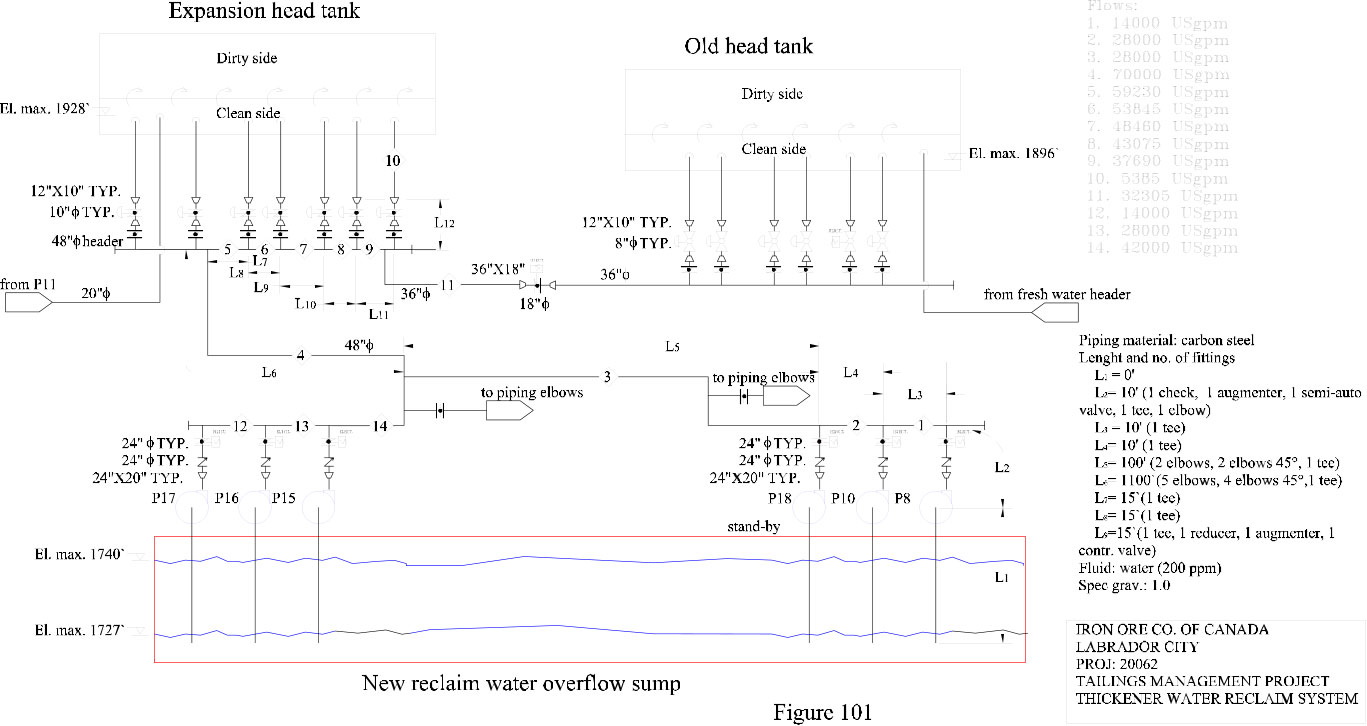
Pump selection starts with acquiring detail knowledge of the system. If you are just replacing an existing pump then of course there is no problem. If you are replacing an existing pump with problems or looking for a pump for a new application then you will need to know exactly how the systems is intended to work. You should have the P&ID diagram and understand the reasons for all the devices included in your system. You should make your own sketch of the system that includes all the information on the P&ID plus elevations (max., min., in, out, equipment), path of highest total head, fluid properties, max. and min. flow rates and anything pertinent to total head calculations.
The next figure is a typical example:
Typical example of flow schematic used for total head calculations.
The control method is important (on-off, control valve, re-circulating, variable speed) as it may affect your selection. Besides the system sketch,[link Point to another website Only the registered members can access]
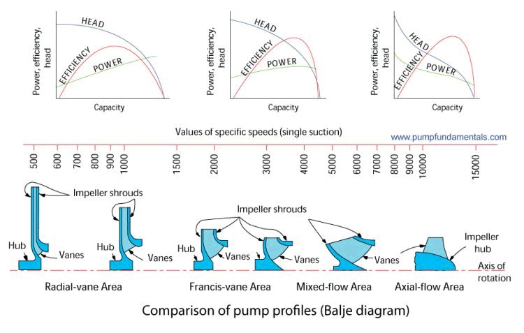
Depending on the industry or plant that you work in, you will be forced to either select a certain type of pump or manufacturer or both. Manufacturers are normally a very good source of information for final pump selection and you should always consult with them, do your own selection first and confirm it with the manufacturer. They can help you select the right type, model, and speed if you have all the operating conditions and if not they will rarely be able to help you.[link Point to another website Only the registered members can access]
Aside from the normal end suction pump, vertical turbine and submersible pumps, there is a[link Point to another website Only the registered members can access]
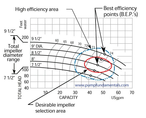
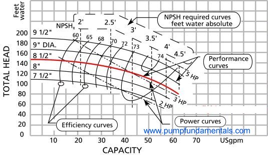
In the selection process, you will be trying to match your flow rate with the B.E.P. of the pump. It is not always possible to match the flow rate with the B.E.P. (best efficiency point), if this is not possible, try to remain in the range of 80% to 110% of the B.E.P..
Desirable selection area for impeller size for centrifugal pumps.
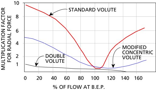
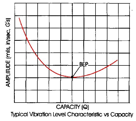
Operating outside this range will lead to excessive vibration, recirculation and cavitation, see the next two figures. The first one from the Pump Handbook from McGraw-Hill which shows how the axial force increases with the distance in terms of percent flow from the B.E.P. and the second from Goulds essentially shows the same information but in terms of vibration.
Radial force vs. % flow of BEP
Vibration level vs. flow
Electronic pump curves have been created for many (over 50) manufacturers, . They have all been developed by Engineered Software located in Lacey Washington USA of which I am a representative. Their pump sizing software PUMP-FLO can help find the best pump for the application, it can select the closest one to the B.E.P. for you and do all kinds of searches based on NPSHR, efficiency, size, etc.
When you order your pump make sure that the motor is installed with spacer blocks so that the next largest motor frame can be installed.

 Reply With Quote
 of it in WAV format, courtesy of my friend Normand Chabot, water hammer specialist here in Montreal.
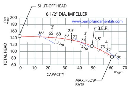

Bookmarks